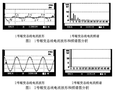
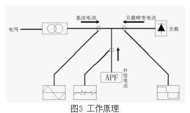
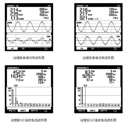
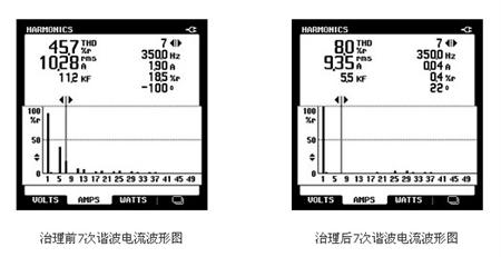
With the rapid development of the industrial economy and the continuous advancement of science and technology, a large number of DC equipment, variable frequency speed control equipment and other non-linear loads are widely used, and the power quality requirements of the power supply system are getting higher and higher. The generation of high-order harmonics increases the harmonic loss of the electrical energy and reduces the power factor of the system. It not only affects the quality of the power grid, but also affects the reliability of the power grid to a great extent. In severe cases, it causes relay protection to malfunction and burns the microcomputer protection. Circuit boards, digital power meters and other microcomputer devices. 1, the phenomenon of failure The 400V power supply system of a cable plant is composed of two European-style box-type substations. The wiring schemes of the two box-changing transformers are the same, but the load of the box-transformers is not the same. Two European-style box-type substations were put into operation shortly. The No. 1 box change occurred when the components of the reactive power compensation cabinet were damaged. The damaged components are mainly capacitor contactors and fuses, in which the capacitor contactors are severely burned. Initially, it was thought that the loosening of the wiring of the capacitor contactor may lead to increased contact resistance. The wiring of the pile head heats up and causes the capacitor contactor to burn out. This causes the fuse on the upper side of the contactor to burn out. The resulting flame also damages the fuse. The company then replaced the burned-out components, checked all wiring pile heads, and improved the reactive power compensation cabinet and continued operation. However, the changed reactive power compensation cabinet has been used for less than a month, and the component damage has again occurred. The location of the damaged components and phenomena is basically the same as the last time. 2. Reason analysis The failures of the two reactive power compensation cabinets occur in Box 1 instead of Box 2. Comparison and analysis of the load of Box 1 and Box No. 2 can be found that the load of Box 2 is basically an asynchronous motor and office lighting. The load, the relative load is small; and the No. 1 box change load has three DC motors in addition to the asynchronous motor, and its power is respectively 185kw, 155kw, 30kw. In addition, there are a large number of heating devices that are controlled by thyristors to control the temperature. The load on the No. 2 box is relatively large. In the event of a failure of the two reactive power compensation cabinets, the crosslinked cable production line of the plant is running, which means that the DC motor and a considerable part of the heating equipment are hung on the low voltage busbars of the No. 1 box. The heating circuit of the plant adopts a three-phase half-controlled bridge rectifier circuit. At the same time, it is necessary to use an AC power supply to supply power to the DC motor. Due to the non-sinusoidal nature of the output waveform of the rectifying device, different phases of the rectifying circuit will generate harmonic currents of different characteristics. For example, the harmonic current generated by a three-phase bridge type 6-phase ripple rectifier circuit is mainly 6 k±1 times (5, 7, 11, 13 times, etc.). Table 1 Current harmonics theoretical data of 6-phase pulsating rectifier Harmonic times n 1 5 7 11 13 17 19 twenty three 25 Harmonic current/% 100 20 14.3 9.1 7.7 5.9 5.3 4.3 4 As a result, cross-linked cable production lines may produce harmonics in Box 1 400V systems during production. Based on the analysis of the load properties and the calculation of the theoretical formulas, it can be determined that there are 6k ± 1 harmonic currents in the No. 1 box-transformer 400V system . In order to confirm and clarify the harmonics and parameters of the No. 1 box-transformer 400V system, multiple comparison measurements were made for No. 1 and No. 2 box changes. The current waveform and spectrogram of No.2 box-transformer bus are shown in Fig. 1, and the current waveform and spectrogram of No.1 box-transformer bus are shown in Fig. 2. Comparative analysis of Figure 1 and Figure 2, the No. 2 box-bus current waveform is a regular sine wave, spectrum diagram analysis also shows that the current basically only contains the fundamental 50Hz current; No. 1 box-bus current waveform is non-sinusoidal, spectrum analysis It can be seen that there are 3, 5, 7 and 11 equal harmonics. The total current distortion THDi is 52.32%, the power factor is 0.8, the system impedance R = 0.1W L = 0.1mH, and the system short-circuit capacity is 10MVA. The reason that capacitor reactive contactors and fuses were damaged several times due to the reactive compensation cabinet No. 1 was caused by the overcurrent caused by the harmonic current generated by the crossover cable production line was amplified by the capacitor of the reactive compensation cabinet. Contactors and fuses are overheated and damaged. 3, harmonic control Harmonic currents not only affect the normal use of reactive power compensation cabinets, resulting in increased power costs for reactive power. Harmonic pollution increasingly threatens the safety, stability, and economic operation of power systems. It also gives linear loads to the same network and other users. It has greatly influenced. Harmonics have been accompanied by electromagnetic interference and power factor reduction and are classified as the three major hazards of the power system. Therefore, it is of great significance to understand the principle of harmonic generation and to study the elimination of high-order harmonics in power supply and distribution systems to improve the quality of power supply and ensure the safe and economical operation of power systems. Harmonic measurement is an important branch of harmonics and plays an important role in suppressing harmonics and solving harmonic generation problems. Therefore, the measurement and analysis of harmonics is an important task in power system analysis and control, and it is an important prerequisite for relay protection and fault measurement. The main measures for suppression and suppression of harmonics in the power system include: raising the voltage level of the power supply; increasing the short-circuit capacity of the system; increasing the number of ripples of the converter device; improving the operation mode of the system, setting the AC filter, etc. Harmonic components. For this cable plant, we can consider setting up an active filter because the scheme of the power supply system has been finalized. The benefits of setting up APF include: improving system power environment and improving power quality; increasing system power factor, reducing reactive payments, and bringing economic benefits; improving load balance of three-phase system, reducing N-line current, and improving system stability Sex. 3.1 The working principle of active filter: ANAPF series active power filter devices are connected to the power grid in parallel and detect harmonics and reactive components of the load in real time. PWM inverter technology is used to generate one current harmonic component and reactive component from the converter. The reverse component is injected into the power system in real time, so that harmonic control and reactive power compensation are achieved. The principle is as follows: ANAPF series active power filter device main technical features: DSP + FPGA all-digital control, has a very fast response time; advanced main circuit topology and control algorithm, higher precision, more stable operation; a machine can be more than Complement harmonics, and can also make up for reactive power; Modular design, easy production debugging; Convenient parallel design, convenient expansion; With perfect bridge arm over-current, protection function; Easy to use, easy to operate and maintain. 3.2 ANAPF technical parameters: Wiring Three-phase three-wire or three-phase four-wire Access voltage 3×380V ±10% Access frequency 50Hz ±2% Dynamic compensation response time Full response time <20ms; On-off level 10kHz Function settings Only harmonics are compensated, only reactive power is compensated, both harmonics are compensated and reactive power is compensated; manual and automatic switching are performed. Harmonic compensation times 2-21 times Type of protection DC over-voltage IGBT over-current device temperature protection Overload protection Automatic current limit in the set value, no overload occurs cooling method Smart air cooling noise < 65db (in the cabinet and operating in the rated state) Working temperature -10°C to +45°C Working environment humidity <85%RH non-condensing Installation occasion Indoor installation Altitude ≤1000m (for use at higher altitudes) Incoming and outgoing ways Down in and out Protection level IP20 Intelligent communication interface Add-on modules Remote monitoring Optional 3.3 ANAPF Active Filter Quotation and Component List Model Number: ANAPF100-400/B Reference price: 120,000 yuan/set The main product details: No. Name Model number Quantity 1 APF electrical cabinet 800X600X2200 1 2 Converter APFCOV-CVT100 1 3 Controller APFMC-C100 1 4 Reactor APF-RE.(S)DG-100 1 5 Active current transformer LT208-S7 3 6 filter DL-1TH1 2 7 breaker CVS160FTM160D4P3D 1 8 Contactor LC1D150M7C 1 9 MCB NDM1-63C32 1 10 Intermediate relay MY4NAC 2 11 R type transformer R320-0.38/0.22 1 12 Harmonic Detector ACR350EGH 1 13 wire 16mm2 Some 14 wire 4mm2 Some 4, governance effect The following is a comparison chart of single-phase power, 5th harmonic current and 7th harmonic current before and after compensation: During the APF operation, the harmonic current generated by the DC motor and the three-phase bridge-type 6-phase ripple rectifier is well suppressed, especially the 5th and 7th harmonic currents with high harmonic content are eliminated. . Now that the equipment is operating well, harmonic hazards can be effectively controlled. references: [1] Chen Zhiye. Yin Huali. New technologies for power quality and its treatment [J]. Power System Technology, 2002(7). [2]Zhang Hao.Dai Ruizhen. Engineering design method of harmonic suppression. Power System Technology, 2002(6). [3] Shanghai Ankerui Electric Co., Ltd. Product Manual. 2013.01. For more information, please contact! Shanghai Ankerui Electric Co., Ltd. Contact: Xu Shuang Telephone 18321975993 E-mail: QQ Hoisting Mechanism And Spare Parts
A Tower Crane has three main mechanisms, that is hoisting mechanism, slewing mechanism and trolleying mechanism.
Hoisting Mechanism and Spare Parts mainly include Tower Crane Lift Motor ( Tower Crane Hoist Motor ), Tower Crane Axial Fans, Tower Crane Hoisting Reducer, Winding Drum, Steel Wire Rope , Safety Brake and other related spare parts. The mechanism has the advantage of compact structure, stable operation, low noise and long service life, ect.
Other spare parts for tower crane: Steel Structure ( Mast Section , Fixing Angle , Anchorage Frame ,etc.), Tower Crane Cabin , Load Moment Indicator , Tower Crane Telescoping Hydraulic System, Tower Crane Gear , Brake Disc , Wire Rope, Tower Crane Power Cable, Electric Parts , Tower Crane Pulleys , Tower Crane Control Console
Hoisting Mechanism,Tower Crane Lift Motor,Tower Crane Axial Fans,Tower Crane Hoist Motor, Tower Crane Hoisting Reducer
SHEN YANG BAOQUAN BUSINESS CO., LTD , https://www.sczenghui.com