Application of ABB 800XA in 200t/h CFB Boiler
Circulating fluidized bed boiler (CFBB) is a device for producing steam by burning fossil fuels with circulating fluidized bed. It has the advantages that the pulverized coal boiler can not match: wide combustion adaptability, low pollution combustion, high desulfurization efficiency, and high combustion heat intensity Large, small furnace volume, high bed heat transfer coefficient, good load regulation performance, and comprehensive utilization of ash residue. Therefore, since its own inquiry, it has been rapidly promoted and developed at home and abroad. However, due to the characteristics of the circulating fluidized bed boiler, it is different from a pulverized coal furnace in operation and operation. If it cannot be controlled quickly and accurately during operation, it is extremely easy. Acid accident. Therefore, in order to better improve the boiler efficiency and reduce emissions pollution, the use of an excellent control system to enhance the working stability and increase the degree of automation is the most important thing to achieve safe and efficient production of boilers.
1 Project Overview Indonesia's Jinguang Group Jiangbi Paper LPPPI is located in the LontarPapyrus pulp and paper mill in Sumatra, Indonesia (North) and is a company dedicated to the pulp, paper, and chemical industries. The plant has a total of 2 alkali recovery boilers (RB) with steam capacity of 440t/h and I75t/h, two 160t/h multi-fuel boilers (MB), and one 110t/h pulverized coal boiler (PCB). 5 turbine turbine generators, 2 GT (Gas Turbine) generators and 7 emergency diesel generators. Due to the unbalanced steam power in this plant, there is an urgent need to build a 220 t/h circulating fluidized bed boiler and to allocate 30 MW of air-cooled steam. Rotary generators to solve this problem, to meet the entire plant production. Living electricity and production steam problems. The project is contracted by Sichuan Dongfang Boiler Industrial Boiler Group Co., Ltd. Chongqing Chuanyi Control System Co., Ltd. is responsible for providing the ABB800xA DCS system, and completes the DCS design and configuration and on-site commissioning work.
System Features of the 2800XA Industrial Information Technology (IndustriallT) is ABB's patented concept. The concept is designed to characterize its characteristics in an open control system that integrates information needed for product service and product operation, maintenance and maintenance. . The 800xA system (ControllT/OperatelT) is a world-class all-around integrated tamper control system that integrates the advantages of traditional DCS and PLC and supports a variety of international fieldbus standards. It not only has the complex analog loop adjustment capability of DCS, friendly human-machine interface (HMI) and convenient engineering software, but also has high-speed logic and sequential control performance with high-end PLC indicators. The system can connect conventional I/O, Profibus, FF, CAN, Modbus and other fieldbus installations. The system has a high degree of flexibility and excellent extensibility. Whether it is the control of small-scale production devices, or the ultra-large-scale integrated control of the entire plant, even for the cross-plant management and control applications, the system can cope with ease.
3 System Configuration This project is equipped with 3 pairs of PM861 redundant controllers at the process level. One pair is used for the furnace safety monitoring system FSSS and the common part of oxygen removal. It is used for the DAS of the data acquisition system, the MCS of the simulation control system, and the sequential control system. The SCS section, a pair of monitoring and control sections for the turbine section. Communication between DCS control system and other systems, such as SIS, AGC, TSI, DEH, and turbine emergency shutdown system ETS) and other auxiliary equipment PLC control system, etc. use MODBUS communication. There are 1820 I0 points in this project, 28 S800 I/O stations and 15 2200x800x600 control cabinets.
The data collection of this project is based on a server and a client. Two CS server CSs, two domain server DSs, two attribute server ASs, four OS stations for operators, and one ES station for engineering stations are used. Both are Dell's rack-mount PowerEdge R710 series, configured as: CPU clock: Xeon5500 series processor, memory: 4G hard disk: 300G disk array: PERC6/i or SAS6/iRRlDVD, integrated graphics with 8M memory, 22" high Resolution SVGA color display.During the project implementation, Dell's commercial computers showed excellent performance.
System printer is 4: Engineer station configuration 2 Canon A3 format two-color laser printer LBP9100CBN: Station staff record printer LQ-1600K3, alarm event printer can 1980. All its printers have a look at network interface functions.
The network structure of this control system is shown in Figure 1.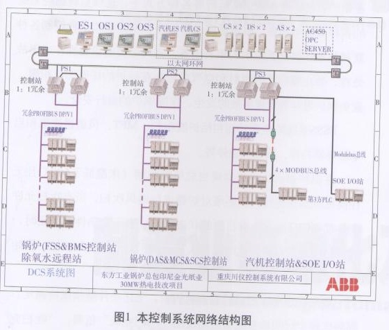
The fieldbus of this project adopts Proflbus-DP communication protocol, and its maximum communication speed is 12MB/S. Profibus-DP cable is connected to the CI854 communication module on the controller through the CI840A communication module on each S800I/O station. To meet the on-site signal acquisition, processing and controller communication. Data acquisition and monitoring use TCP/IP protocol Ethernet, and its communication rate is 100MB/S. The server, operator station, engineer station and on-site process station are connected via Ethernet to meet the server, operator station, and engineer station to monitor, control, and manage the field devices, and to share the number of frames.
4 main functions of the control system 4.1 DAS data acquisition system
DAS is an important part of DCS and it needs to collect and process the most changes in the process. The data acquisition system can continuously collect, process and process the information of all processes of the entire control system, such as input output, intermediate calculation values ​​and status, and operation and abnormal alarms, in a continuous scan cycle, and provides them to the operating personnel in real time. The data acquisition system also completes the storage and processing of process data through software such as historical data, report records, performance calculation, and statistical analysis. The data acquisition system also provides a comprehensive monitoring interface for the entire 800xA system. It can monitor and control all controlled parameters and controlled devices of the plant process through human-machine interaction devices such as CRTs and mice in an automated or manual manner. Processing to ensure that the boiler operates safely and reliably in the best condition. The entire data acquisition system features include:
• Signal processing:
• Display function;
• simulation map;
• Group display;
• Bar graph display;
• Curve display;
• Report S event display and response;
• Historical data display;
• Other displays;
• Record statements;
• System self-diagnosis;
• Performance calculations.
4.2 Analog Control System MCS
One of the main reasons for adopting DCS for circulating fluidized bed boilers is to solve the problem of operational control complexity. The relatively good design of the analog adjustment control loop can effectively control the adjustment actions of the on-site actuators, thereby safely and efficiently controlling the operation of the boiler combustion system.
Circulating Fluidized Bed Boiler is a multi-parameter, multi-variable, strong-correlation, and multi-interference control object. Its automatic control system is both independent and interrelated, which can be described as “moving the whole bodyâ€. When a system is adjusted, other adjustment systems have to be changed accordingly. The adjustment control system of the boiler involves negative pressure regulating water level adjustment, coal feeding regulation and air distribution adjustment, and fully meets the operational control requirements of the circulating fluidized bed.
The adjustment of the water level of the drum (ie, the automatic feed water) is the most important one in the circulating fluidized bed, except for the automatic combustion, and it is also one of the automatic control loops that must be invested in the entire control system. The purpose of the water supply regulation system is to control the boiler water flow so as to maintain the stability of the water level in the boiler drum, so that it floats slightly above and below a certain set value, effectively reducing the manual control of the water level caused by the operator Complications. The feed water control system of the circulating fluidized bed boiler is composed of two main sets of automatic water supply regulation and feedwater bypass regulation. The feedwater by-pass regulation and control system adopts a single-impulse withered section method to control the output of the feedwater by-pass regulating valve through the deviation between the actual value of the drum water level and the set value. The automatic system is generally under the condition that the boiler load is less than 30%. For investment use, the main water supply regulation is divided into two kinds of control methods: single impulse adjustment and three impulse adjustment. The single impulse adjustment and three impulse adjustment control switching are performed by the system after the boiler operation is judged to be self-contained without human intervention. The automatic system is generally used when the boiler is under load (ie, the load is greater than 30%). The three flushing water supply regulation regulates the feedwater control valve through the three signals of the drum water level, the feedwater flow, and the steam flow to maintain the water level of the steam drum. The water level adjustment quality of this system is relatively good. The difference between the steam flow rate and the feedwater flow rate is sent to the feedforward input of the triple-pulse star regulator to form a secondary regulation circuit with a proportional regulation function. The secondary regulation circuit can quickly eliminate the internal disturbance of the feedwater, and the feedwater flow can be quickly followed by the boiler load. (Steam flow) changes synchronously, so that the water level of the drum remains basically unchanged. The main control loop adopts proportional-integral regulation. When the water level of the drum deviates from its set value, the flow of the feed water is changed so that the water level of the drum returns to its set value.
Figure 2 shows the principle of main feed water regulation: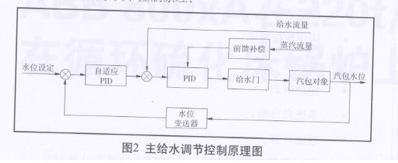
In order to make full use of DCS resources, the safety and reliability of the control system is raised. In addition to the basic functions of the conventional three-fluid level adjustment system, this system also has the following functions:
(1) Single impulse/three impulse automatic switching function When the three signals of the liquid level, feed water and steam are all normal, the regulator is in the state of three impulse adjustment. When any one of the two water or steam nicks is abnormal, the DCS automatically switches from the three-stroke regulated state to the single rush: the regulated state. To prevent boiler water shortage / full pot. An audible and visual alarm was issued to alert the operator of the current working condition of the regulator.
(2) Automatic/manual automatic switching function When the level signal is abnormal, DCS automatically switches from single impulse or second impulse to manual status. The regulator output maintains the output of the previous cycle and emits an audible and visual alarm to alert the operator of the regulator's current operating status.
(3) Drum level compensation Because the saturation of saturated water and saturated steam changes with the pressure of the helium vapor, when using a differential pressure transmitter to measure the level of the drum, different vapor pressures are at the same level. Below, the level of the liquid indicated by the transmitter output is also different. The reason is that the saturated water and saturated steam have a heavy influence and the error is 10% to 15%. In order to overcome the severe effect of saturated water and saturated steam, the drum level compensation function is specially added to reduce the measurement error.
4.3 Sequence Control System (SCS)
The basic purpose of the sequential control and interlocking of the boiler auxiliary equipment is to minimize the adverse effects caused by the working conditions of the lower boiler and auxiliary equipment during normal operation to ensure the long-term use of the equipment. Its main function is to limit the momentary action mode of the fixture by means of a preset protection action when the device does not meet the operating conditions or the unstable or unsafe operating state during normal operation, and ultimately the safety of the device can be guaranteed. The DCS control system of the circulating fluidized bed boiler of this station is equipped with multiple sets of sequence control and interlocking control loops, including induced draft fan, primary fan, secondary fan, high pressure fan, limestone fan, coal feeder, circulating water pump, and slag cooler. The electric door and the steam system's electric and safety doors of the water system.
4.4 Furnace Safety Monitoring System (FSSS)
The main function of the furnace safety monitoring system realized by ABB800xA system is to continuously monitor various parameters and states of the combustion system in various ways such as starting the boiler and stopping the normal operation, and controlling each according to the sequential logic program and the safety interlocking conditions. Interlocking equipment and related equipment in the combustion system to complete the necessary equipment operations or accidents to prevent the explosive fuel and air mixture accumulate in any part of the boiler, to avoid boiler accidents such as explosions, to ensure the safety of the boiler .
The main functions of the FSSS system include furnace purging, MFT, duct burners, start-up and start-up of burners, start-up and shutdown of coal feeders. At each cold start of the boiler or when the total feed trips (the bed temperature is below 600 °C and no burners are running), the furnace must be vented. All purge permission conditions have their own status display on the CRT screen. When all conditions are met, the “purge preparation†light is on. At this time, the operator can press the “start purge†button to start the ventilation purge.
If the above conditions continue to be met within the specified time after the start of purging, the system will automatically issue a “purge complete†signal when the specified time is reached, the “purge complete†light will be on, and the soft logic main fuel trip memory will be automatically reset. Or, the MFTRESET key on the FSSS soft disk can be used to reset the hard logic MFT caused by the loss of the "manual jumper" or the DCS power supply. After the MFTU number is reset, the boiler is ready for ignition. If any condition is lost within a specified time, a "purge interruption" signal is issued, and then a complete purge process must be performed from the beginning after all conditions have been met. The MFT is the highest form of security measures in the FSSS. When there is any situation that jeopardizes the safe operation of the boiler, an MFT action command will be issued to quickly cut off all fuel and materials entering the furnace and send the MFT signal to other systems. Among them, the first signal that directly causes the MFT is the cause of the first trip. The first trip causes will be memorized and displayed on the CRT, and will not be cleared until the start of purge before start or the end of the purge.
5 Conclusion This project completed from the effective date of the contract to completion of the commissioning and lasted 6 months. The 800xA system based on the IndustrialIT control platform fully meets the requirements for the process requirements and modern management of the circulating fluidized bed 220t/h circulating fluidized bed boiler was used by the Jiangpin Paper LPPPI of the Indonesian Jinguang Group and solved the steam before the plant The problem of electricity imbalances satisfies the problem of the use of electricity and gas for production and living, reduces the labor intensity of workers, saves energy, and has a significant effect.
Coated Wire Rope,Color Steel Wire Rope,Coating Steel Wire Rope,Coated Inox Steel Cable
Jiangsu Ruijin Sling Co.,Ltd. , https://www.cnsteelcable.com