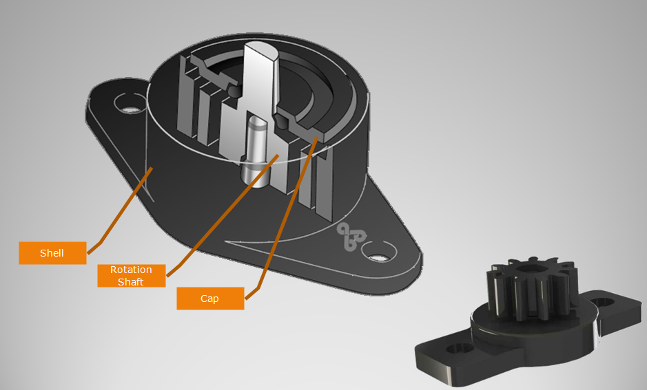
Rotary Damper with gear. Gear Damper is used to dampen drives, control speed, and many other applications. Gear dampers are widely used in automobile interior decoration, household electric appliances,etc. Gear damper increasing equipment life and reducing maintenance expenses.
NOTE:
1. Please contact the corresponding product engineer for specific torque products.
2. Max. rotation speed: 50r/min
3. Max. circle rate: 6 cycle/min(Clockwise360 °, 360 ° anti-clockwise for 1 cycle)
4.Operating temperature: -10~50℃
5.Storage temperature:-30~80℃
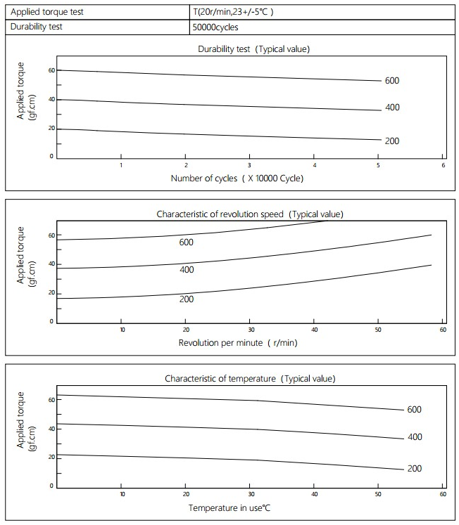
Applied torque: (T)
Test Temperature: 23+/-5℃
Rotating speed:20r/min
Durability test Method: Clockwise 360 °, 360 ° anti-clockwise
Rotating speed:20r/min
Test Frequency: 1cycle/min
Test Temperature: 23±5℃
Durability test cycle: 50000cycle
Test result criteria: Store in the room temperature for 24 hours or more after the test, recording to the torque T=T±30%T.
Gear Damper,Hinge Dampers,Plastic Gear Damper,Small Rotary Gear Damper,Decoration Gear Damper Shenzhen ABD Equipment Co., Ltd. , https://www.abddamper.com To improve the static and dynamic stiffness of the machine tool The positioning and machining errors caused by the deformation of the machine tool bed, base, and pillars are determined by their structural rigidity, and these errors cannot be artificially adjusted and compensated in the machining process. Therefore, the elastic deformation caused by the mass of the moving parts and the cutting force must be controlled to the minimum to ensure the required machining accuracy and surface quality. For some, measures must be taken to improve the structural rigidity of CNC machine tools.
1) Reasonable selection of the structure of the support structure After the support structure is loaded by bending and torsion, the magnitude of its deformation depends on the bending moment of moment of inertia of the section. Cross-sectional area equivalent to switch the same section, should reduce the wall thickness, increase the profile of the cross-section dimensions: torsion selection round wearing surface, bending selected side cross-section; support the cross-section of the closed type as possible, when the hole in the side wall Adding a flange around the hole can increase the bending stiffness. Reasonably arranging the ribs of the spacers of the supporting member can improve the rigidity of the members. The spacers and the ribs can be arranged laterally, longitudinally or diagonally, which is beneficial to improving the bending moment and the moment of inertia of the members. For the bed layout of the horizontal machine bed, the partitions and ribs should be considered for ease of chip removal. The joint part of the machine tool guide and support is often the weakest part of the local stiffness, Xu Guo guide rail size is narrow, can be used single wall or thickened single wall connection, or increase the vertical rib on a single wall to improve the local stiffness; When the size is wide, the double wall connection should be adopted. Increasing the contact stiffness of the various components of the machine tool can increase the bearing capacity of the machine tool. Scraping is usually used to increase the contact area per unit area; applying a sufficient preload between the interfaces can also increase the contact area and reduce the contact deformation.
2) Reasonable structural layout The heavier moving parts on the bed and upright should be placed in the middle of the components as much as possible, which can reduce the deformation caused by dead weight and cutting force. Take a horizontal boring machine or a horizontal machining center as an example. If the spindle box is hung on one side, the weight of the spindle box will cause bending deformation; the cutting force will cause bending and torsion deformation.
3) Measures to compensate for deformation If the relative deformation size and direction of the force point can be measured or the deformation law of the component can be predicted, corresponding measures can be taken to compensate the deformation to eliminate the influence of the force deformation, and the result is equivalent to the improvement. The stiffness of the machine.
4) Reasonable selection of supporting materials such as bed and pillars of the components, which are welded by steel plate or section steel, has the remarkable feature of reducing the weight and increasing the wind degree. The modulus of elasticity of steel is absolutely twice that of cast iron. Under the premise of the same size as the contour, if the rigidity of the welded part and the casting is the same, the wall thickness of the welded part is only half of the casting. If the required local stiffness is the same, because the local degree of wind is proportional to the cubic of the wall thickness, the thickness of the welded part is only about 80% of the wall thickness of the casting. Filling the damping material such as sand or concrete in the sandwiching wall of the supporting member can effectively improve the damping characteristics and increase the dynamic degree of the supporting member. The direct use of concrete, resin concrete or artificial granite as support material can significantly improve the vibration resistance of the support and improve the machining accuracy of CNC machine tools.

