Explore our complete guide of steel flanges, which will make you deeply understand what exactly steel flange is and according to that you can choose it as per your requirement of applications.
It is usually attached to other pipe fitting by using welding attachments and sealed to other flanges by using bolts and gaskets. Flange, connects various things that we use regularly in industrial process, such as for using in water pipelines to oil filtration machinery, food processing manufacturing and pressure vessels, etc.
All these industrial elements were manufactured in various specifications over years and each offer crucial role and their roles expands over several industries.
It is essential to keep the pipes connected safely in order to avoid leakages in the piping system. Flanges keeps the pipe connected accurately and help it work safely for a longer duration.
Table of contents
Steel Flanges Specification
Different Types of Flanges
Steel Pipe Flange Material Grades
Galvanized Pipe Flange Working Pressure
Steel Flange Dimension Chart
WNRF Flange Weight Chart
Steel Flange Face Types
Reducing Weld Neck Flange Thickness Chart
Steel Pipe Flange Pipe Flange Torque Chart
Weld Neck Pipe Flange Bolt Chart
Steel Flanges Specification
Steel Flanges Size
1/2" to 24"
Flange Face Types
Flat
Raised
RTJ
WNRF Flange Standards
ASME B16.5
Steel Pipe Flange Pressure class
150 to 2500
Steel Flanges Types
Blind
Weld neck
Socket weld
Lap joint
Galvanized pipe flange
Threaded
Reducing weld neck flange
Slip on flanges
Steel Flanges Manufacturer in India, Buy Weld Neck and Galvanized Pipe Flange in Different Sizes at Lowest Price in India
Manufacturing standard of pipe flanges is ASME B16.5
It includes NPS ½ to NPS 24 metric inches, which covers of pressure-temperature ratings, dimensions, tolerance, materials, sizes, tolerances, marking, testing, and opening method of flanges.
The flange class rating includes of 150, 300, 400, 600, 900 and 1500 are available in sizes from NPS ½ to NPS 24 metric inches, and flange class rating of 2500 are available in sizes NPS ½ to NPS 12 are in metric and U.S common units with diameter of bolts and flange bolt holes stated in inch units.
ASME B16.5 flange is made from forged or cast materials. Blind flanges and specific reducing flanges are fabricated from forged, cast or plate materials. In this standard also includes requirements and suggestions with regards to flange bolting, flange gasket and even flange joints.
Different Types of Flanges
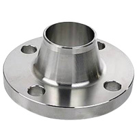
Weld Neck Flanges
This kind of flange is welded to the pipe ends at the neck
Typically butt welded to a pipe
Applied in high pressure situations
Greater longevity than slip-on flanges when subjected to stress
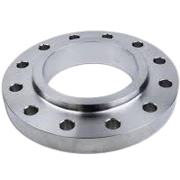
Slip On Flanges
This pipe flange slip over the pipe
Lower Price than weld neck flange
Manufactured with an ID that is slightly bigger than the pipe’s OD
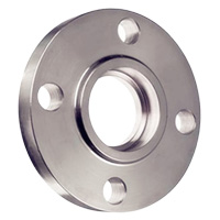
Socket Weld Flanges
It has a female socket in which pipe is fitted
Fillet welding is done from OD on the pipe
Similar to slip-on flange, but with a bore and a counter bore dimension
Counter bore is than the O.D. of the matching pipe
Suitable for pipes with a nominal dia of 150 or less
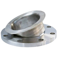
Lap Joint Flanges
Used on piping fitted with lapped pipe (lap joint stub ends)
Having two components: stub end and a loose backing flange Stub end
Similar to a slip-on flange, but with a radius where the flange face and bore meet
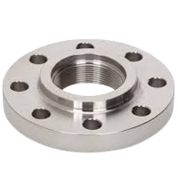
Threaded Flange
Also known as screwed flange
Possessing a thread within the flange bore that aligns with the pipe’s male thread
Used in utility services such as air and water
Like to the Slip-On flange, but the bore is threaded
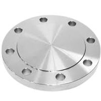
Blind Flange
A blind flange is a round plate with no centre hole and all the necessary boltholes
Used to close off the ends of a piping systems
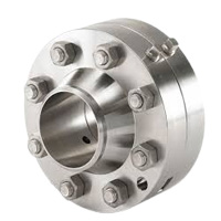
Orifice Flange
Used with orifice meters
Measuring the liquid or gas flow rate in the appropriate pipeline
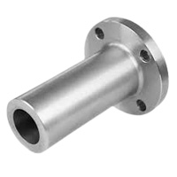
Long Welding Neck Flange
Has a very long neck
Has a tapered neck and a bevel end
Has a straight short pipe as the neck of a long weld neck flange
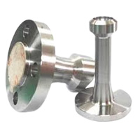
Weldoflange and Nipoflange
A Welding Neck flange combined with a purported Weldolet or Nipolet
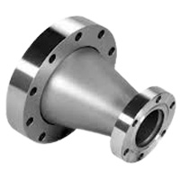
Expander and Reducing Flange
Used to increase or decrease the bore size of a pipeline
A strong substitute for butt weld reducers
Steel Pipe Flange Material Grades
Material
Grades
Features
Carbon steel
ASTM A105
A350 LF2
High tensile strength
Good corrosion resistance
Stainless steel
304
304L
316
316L
317
317L
Superior corrosion resistance
Excellent corrosion resistance
High temperatures
Alloy steel
ASTM A182
F5
F9
F11
F22
F91
High-pressure
High-temperature
Duplex
S31803/2205
Superior corrosion resistance
Super duplex
S32750/2507
High Strength
Excellent corrosion resistance
Nickel Alloys Flanges
Monel 400
Inconel 600
Alloy 625
Excellent mechanical properties
Reducing weld neck flange have pressure rating of class 150 to class 2500
ASME creates the flange class, taking into account there are several pressure and temperature ratings. There are seven classes i.e. 150, 300, 400, 600, 900, 1500 and 2500. And the reducing weld neck flange can be worked at this pressure rating of class. The pressure rating specifies the highest tolerable pressure at a stated temperature. For instance, a class 2500 flange can resists more pressure and it is heavier compared to 1500 flange. Here, the class 2500 flange signifies that the flange is workable at this rated temperature without getting crack or damaged.
Galvanized Pipe Flange Working Pressure
Working Pressure Bar [psi]
Temp (°C)
(°F)
29 – 38
(-20.2 – 100)
50
-122
100
-212
150
-302
200
-392
250
Class
150
19.6
-284
19.2
-278
17.7
-257
15.8
-229
13.8
-200
12.1
300
51.1
-741
50.1
-723
46.6
-675
45.1
-654
43.8
-635
41.9
400
68.1
-987
66.8
-968
62.1
-900
60.1
-871
58.4
-846
55.9
600
102.1
-1480
100.2
-1452
93.2
-1351
90.2
-1307
87.6
-1270
83.9
900
153.2
-2220
150.4
-2180
139.8
-2026
135.2
-1959
131.4
-1904
125.8
1500
255.3
-3700
250.6
-3632
233
-3377
225.4
-3267
219
-3174
209.7
2500
425.5
-6167
417.7
-6054
388.3
-5628
375.6
-5443
365
-5290
349.5
Temp (°C)
(°F)
-482
300
-572
325
-617
350
-662
375
-707
400
-752
Class
150
-175
10.2
-148
9.3
-135
8.4
-122
7.4
-107
6.5
-94.2
300
-607
39.8
-577
38.7
-561
37.6
-545
36.4
-528
34.7
-503
400
-810
53.1
-770
51.6
-748
50.1
-726
48.5
-703
46.3
-671
600
-1216
79.6
-1154
77.4
-1122
75.1
-1088
72.7
-1054
69.4
-1006
900
-1823
119.5
-1732
116.1
-1683
112.7
-1633
109.1
-1581
104.2
-1510
1500
-3039
199.1
-2886
193.6
-2806
187.8
-2722
181.8
-2635
173.6
-2516
2500
-5065
331.8
-4809
322.6
-4675
313
-4536
303.1
-4393
289.3
-4193
Standard size range of socket weld and slip on flanges is 1/2″ to 24″
The range of standard size socket weld and slip on flanges are important for several industries as it gives fastening to the piping system. Socket weld and slip on flange are usually manufactured in the standard from ½†to 24â€.
The categorization and distinction between the flanges from countries to countries are important to understand for flawless combination and consistency in global projects.
Flange standardization gives safety and similarity in the broad range of global industries. It enables global trade by offering a common base for fabricators, suppliers and consumers.Â
Steel Flange Dimension Chart
NPS
01/2
03/4
1
1 1/ 2
2
3
4
5
6
O.D.(Inch)
3.5
3.88
4.25
5
6
7.5
9
10
11
SORF Bore Inner Dia (MM)
9.65
11.17
34.54
49.53
61.97
90.67
116.07
143.7
170.68
Bolt Holes No
4
4
4
4
4
4
8
8
8
Holes Dia (MM)
15.74
15.74
15.74
15.74
19.05
19.05
19.05
22.35
22.35
Bolt Circle (Inch)
2.38
2.75
3.12
3.88
4.75
6
7.5
8.5
9.5
WNRF Bore Inner Dia (MM)
22.35
27.68
26.67
40.89
52.57
77.97
102.36
128.2
154.17
Dia Hub Base (Inch)
15.74
20.82
1.94
2.56
3.06
4.25
5.31
6.44
7.56
Min WT (MM)
1.19
1.5
12.7
15.74
17.52
22.35
22.35
22.35
23.87
RF Dia(Inch)
1.38
1.69
2
2.88
3.62
5
6.19
7.31
8.5
NPS
8
10
12
16
18
20
22
24
O.D.(Inch)
13.5
16
19
23.5
25
27.5
29.5
32
SORF Bore Inner Dia (MM)
221.48
276.35
327.15
410.46
461.77
513.08
564.38
615.95
Bolt Holes No
8
12
12
16
16
20
20
20
Holes Dia (MM)
22.35
25.4
25.4
28.44
31.75
31.75
35.05
35.05
Bolt Circle (Inch)
11.75
14.25
17
21.25
22.75
25
27.25
29.5
WNRF Bore Inner Dia (MM)
202.69
254.5
304.8
387.35
438.15
488.95
539.75
590.55
Dia Hub Base (Inch)
9.69
12
14.38
18
19.88
22
24.25
26.12
Min WT (MM)
26.92
28.44
30.22
35.05
38.1
41.14
44.45
45.97
RF Dia(Inch)
10.62
12.75
15
18.5
21
23
25.25
27.25
WNRF Flange Weight Chart
NPS
1/2
3/4
1
1¼
1½
2
3
4
5
WNRF (KG)
0.9
0.9
1.4
1.4
1.8
2.7
5.2
7.4
9.5
SORF (LBS)
1.1
1.98
1.98
3.08
3.08
5.07
9.03
13
14.99
BRF (LBS)
1.98
1.98
1.98
3.08
3.96
5.07
9.03
16.97
19.84
NPT (KG)
0.5
0.9
0.9
1.4
1.4
2.3
4.1
5.9
6.8
LJRF (KG)
0.5
0.9
0.9
1.4
1.4
2.3
4.1
5.9
6.8
SWRF (LBS)
1.98
1.98
1.98
3.08
3.08
5.07
9.03
13
14.99
NPS
6
8
12
14
16
18
20
22
24
WNRF (KG)
11.7
18.9
39.6
51.3
63
74.3
88.7
101.3
120.6
SORF (LBS)
18.95
29.76
63.49
89.28
105.16
128.97
163.8
183.64
218.25
BRF (LBS)
26.89
46.73
122.13
138.8
178.57
218.25
282.85
352.29
426.59
NPT (KG)
8.6
13.5
28.8
40.5
44.1
58.5
74.3
83.3
99
LJRF (KG)
8.6
13.5
28.8
47.3
63
72
87.8
110.3
123.8
SWRF (LBS)
18.95
29.76
63.49
89.28
97.22
128.97
163.8
183.64
218.25
Steel pipe flanges are available in different faces like RF, FF and RTJ
These are the three most important and most commonly used types of flange faces.
A raised face flange has a circular shape sealing face which extends from the flange bolting circle plane. It is available in all pressure class, therefore it is utilize for a broad range of temperature and pressure ratings. Its prime purpose is to compress more pressure on a smaller gasket part, whereby it increases the pressure capability of the joint. It is most commonly used for oil, gas and chemical engineering industries.
As its name signifies flat face flange doesn’t have any lump or raised surfaces. It utilize a “full face†gasket and have a large exposure sealing area. It is easy to align while installation and are usually more cost-effective as compared to other type of flanges. This type of flange face is the easiest method to protect against from damages and rust. It is used by applying adherent or magnetic flange guard.
Ring-Type Joint flange are usually used for more critical applications, mainly for high pressure or temperature applications. It is fabricated to offer a leak proof seal in critical conditions where standard gasket can fail. The surface of this kind of flange are machined groove.
Steel Flange Face Types
Plain Face/ Flat Face Flange
non-metallic gaskets
serrated sealing surface
low pressure applications
pressure classes 125 and 250
Raised Face Flange
classes 150 and 300
Height: 1/16 inch (1.6mm)
class 300: 1/4 inch (6.4mm) raised face
Ring-Type Joint (RTJ)
high pressure systems((>750â°C / 1,382â°F))
typically used for class 900 and above
Groups: R, RX and BX
Flange Face Type
Characteristics
Gasket Type
Sealing Face
Sealing Area
Pressure Class
Pressure Range
Temperature Range
Flat Face
Soft. Non-metallic.
Inner diameter to outer diameter.
Large
125#, 250#
Narrow. Low pressures only.
Narrow. Low temperatures only.
Ring-Type Joint
Hard.Â
Groove in flange face.
Small
All. Generally ≥ 900#.
Broad. Generally used for higher pressures.
Broad
Raised Face
Non-metallic, semi-metallic.
Inner diameter to raised face outer diameter.
Medium
All.
Broad
Broad
Check thickness and torque specs of plate flanges6
The thickness of the plate flange has a prime effect on the hardness and toughness of the connection. Which means as that, if the thickness of the flange is higher its toughness will greater and vice-a-versa.
The torque of plate flange, is the force which it can bear, a rotational force or the ratio of strength demanded to rotate an item. It is considered as the turning force utilize to move items which includes of bolts.
The torque of plate flange is essential to know the prolong life of flange. It gives a non-failing connection, such as for leak free liquid transmission, accurate gasket installation, and bolts must be screwed on the flange with accurate tension and balance over the complete face of the flange. It helps to secure two elements so that it can prevent pulling or slipping apart.
A Backhoe Loader , prominently featured on Google's Construction Machinery Independent Station, is a versatile machine essential for a wide range of construction and excavation tasks. Combining the capabilities of a Bulldozer and an Excavator , it excels in both digging with Excavator Parts like Hitachi Excavator Parts and loading operations with Wheel Loader Parts such as XCMG Wheel Loader Parts. This dual functionality makes it highly efficient on job sites where space is limited or versatility is required.
Backhoe Loaders are equipped with a front loader bucket for loading materials and a rear digging arm, similar to those found on Tractor Bulldozer and Small Dozer, with an attached excavator bucket for digging. This enables them to handle diverse tasks from digging trenches and foundations to loading trucks and backfilling. Their compact size and maneuverability, comparable to a Mini Backhoe Loader, make them suitable for urban construction projects and roadside maintenance.
Attachments like XCMG Motor Grader Parts enhance their utility, allowing for grading and leveling surfaces with precision. These machines are powered by engines from reputable manufacturers such as Cummins Engine Parts or WEICHAI Engine Parts, ensuring reliability and efficiency in demanding environments.
Regular maintenance and access to Truck Parts near me are crucial for minimizing downtime and optimizing performance. Backhoe Loaders are designed to withstand rugged conditions, supported by robust components like SANY Excavator Parts and Komatsu Excavator Parts. This combination of durability, versatility, and power makes Backhoe Loaders indispensable in the construction industry, facilitating efficient and productive operations across various job sites.
Skid Steer Loader,Mini Skid Steer Loader,skidsteer tracks,skidsteer for sale